
Supply chain issues may cause delays.
Click for details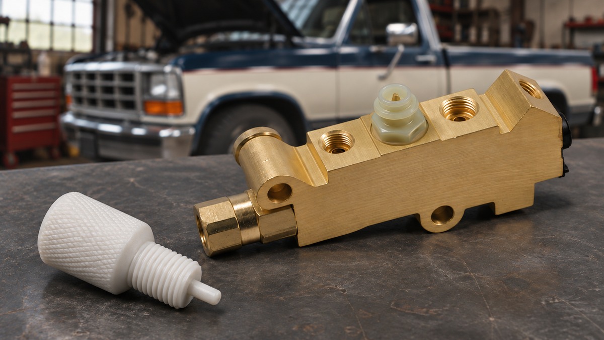
The right Ford proportion valve matches the brakes, hydraulic lines, and warning switch on the truck in front of you. The year and model get you started. The parts on the truck finish the job. A previous owner may have changed the rear axle, converted the front brakes to discs, or installed a different master cylinder. Even a stock-looking Ford can have a mix of original and replacement hardware under the hood.
Before you order, take a photo of the existing valve with its lines still attached. Then compare the truck and the replacement at the wheels, at the valve ports, and at the electrical connector. That comparison will also help you decide whether to put a proportioning valve bleed tool on your parts list.
Look at the hardware at the wheels and record what’s there. A front disc and rear drum setup calls for a valve specified for that layout. A rear disc conversion changes the brake system you’re working with, so use the conversion kit manufacturer’s guidance to match the valve to the front and rear hardware. If the truck still has drums on both axles, check the factory service information to identify the original valve or pressure warning assembly before shopping.
The distinction matters during harder stops. As weight transfers forward, the rear tires have less grip available for braking. A proportioning valve limits how quickly rear brake pressure rises above a calibrated point, helping manage rear-wheel lockup. A combination valve may also house the pressure-differential switch that triggers the dash warning light. Two valve bodies can look similar and serve different brake systems.
Once you’ve confirmed the layout, compare our Ford truck proportioning valves by year, model, and brake configuration. Keep the conversion kit information handy if the truck has been modified. For a stock restoration, the factory service manual or parts catalog can help you match the original application.
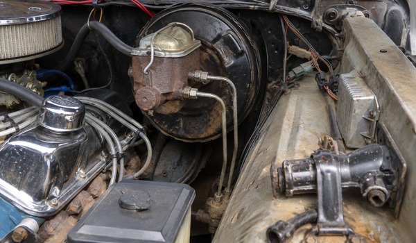
Follow each line from the existing valve and note where it goes. Take a wide photo showing the valve and master cylinder, then get close-ups of the fittings and mounting bracket. If there’s a legible part number on the valve, include it in your notes. Those details help when a listing shows a different port arrangement from the one on your truck.
Check the port threads and the flare seats against the replacement specifications. The threads hold the fitting in place, and the flare and seat form the hydraulic seal. You also need to know where each circuit enters and exits the valve. Use the replacement valve’s diagram to check routing, especially if the new body is oriented differently on the bracket.
For example, our catalog has separate front-disc and rear-drum listings for 1973–1979 F-100/F-150 and F-250/F-350 pickups. The F-100/F-150 listing flags a possible rear line fitting change. The F-250/F-350 listing calls out changes at the master cylinder connections. Read the notes for the exact part so you can account for any brake-rated fittings or line work before the truck is apart.
If the truck is already in the shop, a short fitment note can save a parts run. For a 1978 F-150, it might read “front discs, rear drums, original master cylinder as far as I can tell, rear fitting size still to verify.” Add your photos and mark anything you’re unsure about. Ask the supplier which port serves the rear brakes and what fitting the replacement takes. You can then check the answer against what’s on the truck and have the right hardware ready when the valve arrives.
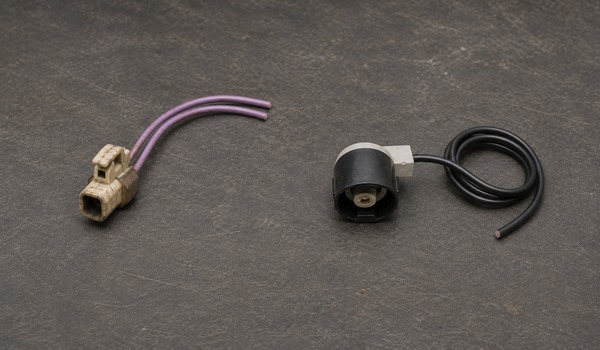
The connector on the truck is one piece of the puzzle. The switch supplied with the replacement valve is another. Some Ford replacement listings include a pigtail to connect the truck’s wiring to the switch on the new valve. Take a clear photo of both connector faces and record the number of wires before unplugging the original assembly. Use the vehicle wiring diagram and the replacement part instructions to confirm the hookup.
This is where terminology can cause confusion. A listing that includes a sensor wire or pigtail is telling you how the warning circuit connects. Bleed tool fitment depends on the valve and the switch opening that the tool threads into. A truck’s original connector can have two wires and a replacement may use a different switch. Confirm the replacement valve’s part number before choosing the tool.
On a compatible combination valve, the Combination/Proportioning Valve Bleeding Tool temporarily takes the place of the brake warning switch. It holds the internal pressure-differential shuttle centered while you bleed the brakes, when opening a wheel bleeder can create a pressure difference between the two circuits.
The tool fits most of the non-adjustable valves we sell. Its stated fitment excludes factory valves and two-wire sensors. If you’re keeping the original Ford valve, follow the service procedure for that assembly. Our 1980–1986 F-250/F-350 disc/drum replacement listing points to this tool as a related item. If you’re using a different replacement, check its exact part number before adding the tool to the order.
Use the manufacturer’s bleeding sequence for the vehicle or brake kit. Once bleeding is complete, remove the tool, reinstall the warning switch, and reconnect the wiring. Verify the warning circuit, check the system for leaks, and confirm a firm pedal before following the manufacturer’s test procedure in a controlled area. Keep the truck parked if the pedal sinks, a connection leaks, or the brake warning light stays on.
Check the specific application for each valve. Pickups from the same year range can have different hydraulic layouts, line connections, and valve calibrations. Match the exact model and brake setup, and compare the replacement’s plumbing diagram to the lines on your truck before assuming the two valves interchange.
The catalog includes a 1980–1986 F-250/F-350 listing and a separate 1984–1986 listing. If both cover the year on your title, use the application notes, port layout, and warning switch to narrow it down. The original valve part number and photos of the lines and connector can help confirm which replacement you need.
Check the actual replacement valve and switch. The tool excludes factory valves and two-wire sensors. A pigtail adapts the wiring, so confirm tool compatibility with the replacement valve’s part number and switch design before buying.
Can't find what you need for your Classic Vehicle? Give us a call at: (336) 337-2132
